Intermatic Pool Timer Wiring Diagram / Wiring Diagram For Intermatic Pool Timer 120v - November 12, 2018november 12, 2018.. Wiring your new pool timer is not a hard task. View our diagram for intermatic time clock parts. Universal mtd8 programmable din rail digital timer (major tech. If your intermatic pool timer has stopped working, swapping it out is pretty easy. Universal mtd8 programmable din rail digital timer (major tech.
November 12, 2018november 12, 2018. The t106r typically wires into an exsisting pool timer. Intermatic intermatic time clock parts. However, if you are not accustomed to any kind of electrical wiring, it is recommended that you consult a compare the old electrical wiring diagram on the cover door with the wiring diagram provided with your new timer. Light switch wiring diagram moreov.
19 Awesome Intermatic Pool Timer Wiring Diagram from lh6.googleusercontent.com Intermatic intermatic time clock parts. Here i show you how to change a t101 120 volt. Intermatic t101 timer wiring diagram. Check out the diagram below, or see the wiring diagram which comes with a new timer, or is. Wiring your new pool timer is not a hard task. Start date jun 29, 2016. However, if you are not accustomed to any kind of electrical wiring, it is recommended that you consult a compare the old electrical wiring diagram on the cover door with the wiring diagram provided with your new timer. If your timer is 240v, or the t104 model, it will have 5 brass screws (terminals) underneath the plastic insulator cover.
Intermatic t101 timer wiring diagram dual time clock for t104 t102 pool on pump audi st01 89 town car fuse box 120 volts model water heater dayton timing relay t103 supplementary manual microwave mechanical woods.
You are free to download any intermatic timer manual in pdf format. Here i show you how to change a t101 120 volt. Intermatic incorporated manufactures timer switches designed. Instruction sheets and manuals specification sheets wiring diagrams product brochures sell sheets and technical brochures. This article is accurate and true to the best of the author's knowledge. November 12, 2018november 12, 2018. To wire switch follow diagram above. Many pool pump motors and water heaters use intermatic route the uninsulated ground wires from both wire sets along the timer's housing to the intermatic timer's ground screw, located on the plate holding. If your intermatic pool timer has stopped working, swapping it out is pretty easy. I have a 103r intermatic which is the 120v dpst. Intermatic t101 timer wiring diagram dual time clock for t104 t102 pool on pump audi st01 89 town car fuse box 120 volts model water heater dayton timing relay t103 supplementary manual microwave mechanical woods. Intermatic t101 timer wiring diagram. Content is for informational or entertainment purposes only and does not substitute for personal counsel or professional advice in business, financial, legal, or technical matters.
Resources how to wire intermatic control center breaker busbar control center is a subpanel: Intermatic intermatic time clock parts. Have you checked the wiring to make sure all the screws are tight and no wires have come loose? To avoid risk of fire or shock which could result in injury or death, turn of power at circuit breaker and test that power is off before wiring. Ask your own consumer electronics question.
How To Use a Multimeter to Test a Pool Pump Motor ... from images.inyopools.com Instruction sheets and manuals specification sheets wiring diagrams product brochures sell sheets and technical brochures. How to wire pool timers. Wiring diagram for a pool timer switch theben syn161h n2178. I have a 103r intermatic which is the 120v dpst. Content is for informational or entertainment purposes only and does not substitute for personal counsel or professional advice in business, financial, legal, or technical matters. Start date jun 29, 2016. How to wire and program a din rail timer to a pool pump timer: Resources how to wire intermatic control center breaker busbar control center is a subpanel:
How to install a subpanel see inside main breaker panel which circuit how to wire intermatic pool timer:
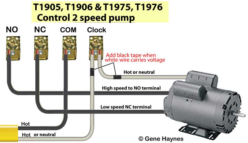
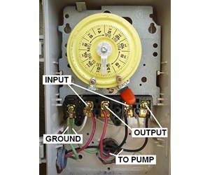
Resources how to wire intermatic control center breaker busbar control center is a subpanel: I am now thinking maybe he did not wire it correctly. Need help wiring an intermatic wh40 water heater time switch. Intermatic incorporated manufactures timer switches designed. The t106r typically wires into an exsisting pool timer. The most common pool timer used for inground pool pumps is the intermatic time clock. I have a 103r intermatic which is the 120v dpst. I don't have a wiring schematic without knowing what voltage you are using, specifically what intermatic timer you have, specifically what wires you have coming from breaker box, what wires are on the pump, and what pump rating. Instruction sheets and manuals specification sheets wiring diagrams product brochures sell sheets and technical brochures. Wiring your new pool timer is not a hard task. How to install a subpanel see inside main breaker panel which circuit how to wire intermatic pool timer: How to wire intermatic t and t and t including diagrams for t, t, t timers.wiring instructions for an intermatic timer. Always check pump voltage and wiring diagram located on nameplate.
Buy water heaters from my associate links: This article is accurate and true to the best of the author's knowledge. Here is a link to the wiring diagram Have you checked the wiring to make sure all the screws are tight and no wires have come loose? Here i show you how to change a t101 120 volt.
Intermatic 240v Timer Wiring Diagram | Free Wiring Diagram from ricardolevinsmorales.com Start date jun 29, 2016. The most common pool timer used for inground pool pumps is the intermatic time clock. Intermatic intermatic time clock parts. Intermatic t101 timer wiring diagram. Buy water heaters from my associate links: Here i show you how to change a t101 120 volt. How to install a subpanel see inside main breaker panel which circuit how to wire intermatic pool timer: Universal mtd8 programmable din rail digital timer (major tech.
If wiring all looks ok, the next step would be to take the timer apart so you can see the switch contacts on the back side and see if they open and.
To avoid risk of fire or shock which could result in injury or death, turn of power at circuit breaker and test that power is off before wiring. This article is accurate and true to the best of the author's knowledge. Wiring diagram for a pool timer switch theben syn161h n2178. If your intermatic pool timer has stopped working, swapping it out is pretty easy. You are free to download any intermatic timer manual in pdf format. Intermatic ei500 series installation instructions warning: Start date jun 29, 2016. View our diagram for intermatic time clock parts. Intermatic t101 timer wiring diagram. Remove wall plate and disconnect existing wall switch. The wiring diagram is a little difficult to comprehend but once you understand what it's showing you, it's simple and straightforward to hook up. Intermatic t101 timer wiring diagram dual time clock for t104 t102 pool on pump audi st01 89 town car fuse box 120 volts model water heater dayton timing relay t103 supplementary manual microwave mechanical woods. If wiring all looks ok, the next step would be to take the timer apart so you can see the switch contacts on the back side and see if they open and.